EVSE Controllers

Smart EV Charge Controller

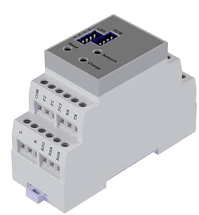
The EPC 3.0 is our most advanced EVSE controller and your gateway to effortless smart EV charging.
It features all the electrical protection mechanisms of EPC 2.0 whilst adding OCPP 1.6j in an industry leading compact form.
EPC 3.0 functionality includes load management, user access control and back-office integrations for remote scheduling and energy monitoring.
The load management capabilities, which can be configured both locally and remotely, protect against overcurrent and optimise the power distribution in a multicharge point system.
The EPC 3.0 EVSE controller is the ideal technology solution for creating a smart EV charge point, whether for domestic or commercial applications.

Direct OCPP Communication

The built in Wi-Fi and OCPP stack allows the Smart EPC 3.0 to communicate with an increasing number of back-office/Smart charge systems easily and gives immediate access to all the features these powerful platforms offer including payments, load management, RS485 communication, charge scheduling, solar charging and access control. Multiple back-
offices systems are already integrated which will simplify establishing a charge point network and keep development costs low.

Product Features

  • IEC 61851-1 Mode 3
  • Supports 1 outlet; Socket or tethered cable
  • 35mm DIN rail mount module
  • Solenoid or motor interlock drive
  • Status LED & external LED support
  • RCM support for >6mA DC leakage
  • PEN Loss detecon
  • Modbus over RS485
  • Local & remote load management capabilies
  • RFID access control support
  • Overtemperature control (adjustable)
  • 2.4GHz Wi-Fi
  • OCPP 1.6j
  • OTA updates

EPC 3.0 - EVSE Controller Specifications

Power Supply
207 -257 V @ 50 Hz AC
Charging Mode
1 x mode 3 according to IEC61851-1 via IEC62196-2 or SAE J1172 (socket or tethered cable outlets)
Charging Current
6A – 32A (configurable & variable)
Wireless
Wi-Fi —802.11b/g/n— 2.4GHz
Wired
RS485(Modbus), CT coil, CP, PP, TTL, Lock Feedback, RGB LED
Optical
RGB LED
EV Connection
Socket Tethered
RCM
Western Automation RCM14-01 Kemet FG-R05-3A
External LED
External RGB LED output connector (0V acve with common 5V)
EV Contactor
Generic contactor support with activation supply on Common input
Aux Contactor
Generic contactor support with activation supply on Common input
Socket Lock
Phoenix Hella PCE
RFID
RF Solutions RFID1-13RTTL-3V
Current Monitoring
CT Coil 100A/50mA (2000:1) Modbus MID Meters Carlo Gavazzi (Selected Models)
External Button
Push button, acvates selected features
Dimensions
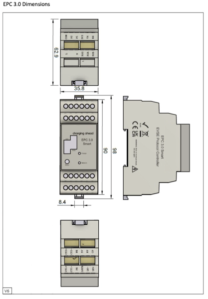
W: 35 mm, H: 91 mm, D: 63mm
Mounting
Standard DIN Rail (35mm)
Enclosure Material
Plastic
Unit weight
150g
Operating Temperature
–25°C to 50°C
User access
None
Colour / finish
White
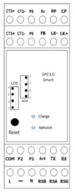
L (Line)
This is where the AC ‘live’ or ‘line’ connection is made (90-264V @ 50Hz AC)*
N (Neutral)
This is where the AC ‘neutral’ connection is made (90-264V @ 50Hz AC)*
–
Not used
0V (PE)
This is where the Protective Earth ( ground ) for the RCM and 0V reference voltage connections is made
LK+
Configuration is dependent: • Provides a drive current to continuously energise the solenoid interlock • Provides a drive current to change the motorised interlock state to locked ( The signal is activated for 500ms and changes to pulsed 500ms intervals until the lock is engaged. ( See LK FB ) Rating 12V 300mA
LK-
Configuration is dependent: • Provides a return path for the solenoid interlock drive current LK+. • Provides a drive current to change the motorised interlock state to unlocked ( The signal is activated for 500ms and changes to pulsed 500ms intervals until the lock is disengaged. ( See LK FB ) Rating 12V 300mA
LK FB
Use this terminal if lock feedback has been selected via Web page. For Phoenix and PCE locks connect to FB and PE terminals
COM
Relay 1 & 2 (common) Live from integrated electrical protection or mains terminals
P1
Relay 1 to coil on the EVSE ( 16A / 32A ) Contactor
P2
Relay 2 to coil on the Auxiliary Contactor
PP
( Proximity Pilot ) Connection for the IEC61851 / J1772 EVSE Connector ( see Proximity )
CP
( Control Pilot ) Connection for the IEC61851 / J1772 EVSE Connector ( see Pilot Circuit )
5V
Reference voltage
CT1+
Connection for the current transformer 1
CT1-
Connection for the current transformer 1
CT2+
Connection for the current transformer 2
CT2-
Connection for the current transformer 2
3v3
Supply for RFID module / Used for Boost button terminal 1
RX
TTL Communication input for RFID
TX
Used for Boost button terminal 2 (Subject to software configuration)
RSA
RS485 connection available in EPC 3.0
RSB
RS485 connection available in EPC 3.0
RSG
RS485 ground connection available in EPC 3.0
Pinouts for JST Connectors - Charge Status LED
Pin 4
5v Common Anode
Pin 3
RGB Blue
Pin 2
RGB Green
Pin 1 (Boom)
RGB Red
Pinouts for JST Connectors - RCM (6mA)
Pin 1 (Top)
Fault
Pin 2
Test
Pin 3
12v
Pin 4
0v
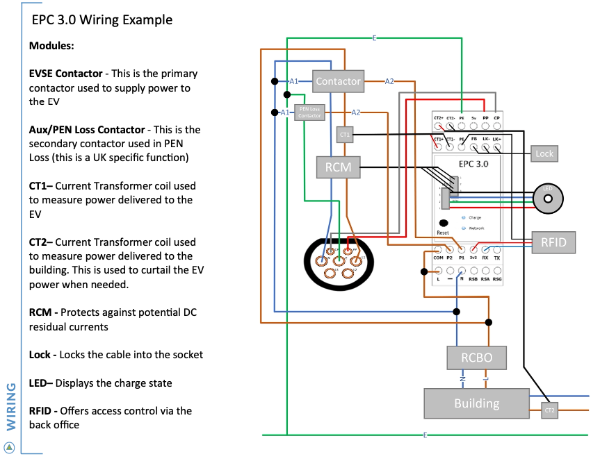
*The inclusion of certain modules may be mandated by law.
Please check the legislaon of your region to ensure you configuration meets the legal requirements. Incorrect wiring of a controller can result in serious consequences, including but not limited to damage to equipment, electrical shock, fire, or other hazards. It is crucial that all wiring and installation tasks are performed by qualified professionals in accordance with local electrical codes and standards.
Charging State
Charging LED
State A; Car not plugged in
Dim Blue
State B; Car plugged in, not requesting charge (Suspended EV)
Bright Blue
State B; Car plugged in, requesting charge (Suspended EVSE)
Pulsing Blue
State C; Car charging (including Boost Charge)
Bright Green
Boost mode ready, car not plugged in
Dim Amber
Boost mode ready, not requesting charge
Bright Amber
State F; Car Fault
Slow Pulsing Red
State F; Diode fault
Flashing Red
RCM fault
Fast Pulsing Red
State E; PEN fault
Pulsing Purple
Current transformer fault
Flashing Purple & Red
Over temperature fault
Flashing Blue & Red
Motor fault / Lock Error
Flashing White
Other error
Bright Red
Copyright © 2026 Cursey Technology Ltd. All rights reserved.

24hr to 48hr BOM to Quotation

Submit your details and we'll get back to you within two business days.
How did you hear about us?